Thread-Forming vs Thread-Cutting Screws for Metal and Plastic
Thread forming vs thread cutting screws differ mainly in how they create the mating thread during installation. A thread-forming screw displaces and reshapes material around the pilot hole without intentionally cutting it away, while a thread-cutting screw uses cutting features to remove material and create the internal thread. This difference affects pilot-hole design, installation torque, chip generation, joint strength, material suitability, and production reliability.
Both types may be described broadly as self-tapping or direct assembly screws because they can create a mating thread during installation. However, “self-tapping screw” is an umbrella term rather than a guarantee of one specific thread-forming mechanism. OEM buyers should therefore specify the actual screw type, material, hole preparation, head and drive, surface finish, and application instead of purchasing only by a generic tapping-screw description.
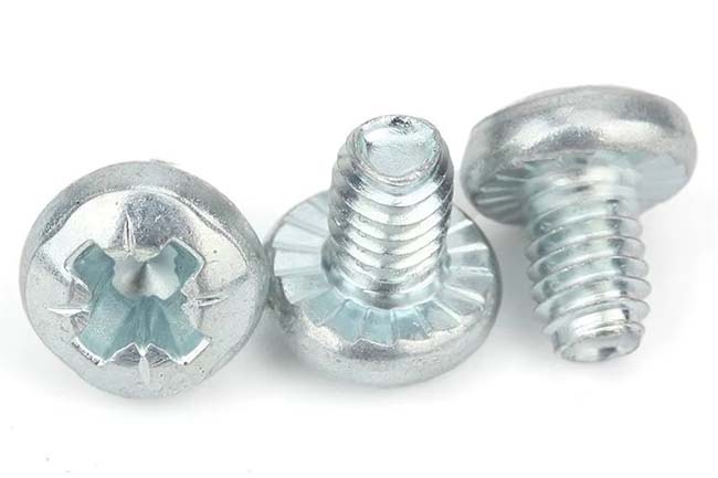
Flybear supplies standard, special, and custom industrial fasteners for machinery, electronics, sheet-metal, automotive, electrical equipment, and other OEM applications. Buyers evaluating direct-thread assembly can review thread-forming screws and provide the mating material, pilot-hole information, screw size, finish, quantity, and assembly requirements for technical review.
Thread Forming vs Thread Cutting Screws: The Core Difference
| Factor | Thread-Forming Screw | Thread-Cutting Screw |
|---|---|---|
| Thread Creation | Displaces material to form the female thread | Removes material with cutting features |
| Chip Generation | Normally designed for chip-free thread formation | Can generate chips or swarf during thread cutting |
| Pilot Hole | Hole diameter must allow controlled material displacement | Hole must allow cutting features to create the mating thread |
| Suitable Materials | Often considered for sufficiently ductile metals and suitable plastics | Can be useful where cutting is preferable to significant material displacement |
| Installation Torque | Includes torque required to deform the mating material | Includes torque required for the cutting operation |
| Main Production Concern | Hole size, material deformation, forming torque, and radial stress | Chip control, cutting torque, hole size, and material removal |
| Typical Decision Driver | Chip-free direct assembly and formed-thread engagement | Reduced material displacement or need to cut a mating thread |
The correct choice depends on the joint rather than the screw alone. Sheet thickness, metal hardness, plastic resin, boss design, pilot-hole diameter, engagement length, installation speed, repeated service requirements, and acceptable chip generation all influence the result.
How a Thread-Forming Screw Works
A thread-forming screw creates its mating thread primarily by plastically displacing material around a prepared hole. Instead of using a cutting flute to remove a significant amount of material, its thread and forming geometry push the mating material into the desired internal-thread shape.
This process is often attractive in automated production because it can combine thread creation and fastening into one assembly operation while avoiding a separate tapping process. Because material is displaced rather than intentionally removed, chip contamination can also be reduced compared with a cutting process.
For metal applications, DIN 7500-1:2021-07 is a current standard covering thread-forming screws for ISO metric thread within its stated scope. DIN 7500-2:2016-04 provides guideline values for pilot-hole diameters for relevant thread-forming screws. Importantly, those hole dimensions are guidance rather than universal values; actual hole preparation, mating material, engagement length, and production conditions still require validation.
Why Pilot-Hole Diameter Is Critical
The pilot hole controls how much material the screw must displace. If the hole is too small, forming torque may become excessive, the screw may be damaged, or the mating component may deform or crack. If the hole is too large, thread engagement may be insufficient and the internal thread may not provide the intended stripping resistance.
Hole production also matters. A drilled hole, punched hole, cast hole, or molded hole can have different dimensional accuracy, surface condition, taper, and local hardness. For high-volume production, the assembly should be tested using actual production components rather than assuming that one nominal pilot-hole diameter will behave identically with every manufacturing process.
How a Thread-Cutting Screw Works
A thread-cutting screw contains one or more cutting features that allow the screw to machine its mating thread as it is installed. Material is removed rather than primarily displaced, which means chips can be generated during assembly.
DIN 7513:2016-12 is a current DIN standard covering specified heat-treated metric thread-cutting screws with hexagon and slotted head configurations. DIN 7516:2016-12 covers specified cross-recessed thread-cutting screw configurations. These standards illustrate why buyers should not treat “thread cutting screw” as one universal product geometry: head style, cutting feature, thread, material condition, and other requirements may depend on the applicable specification.
Thread-cutting screws can be considered where forming the mating material would create excessive deformation or where the application specifically requires a cutting action. However, chip generation needs attention in electrical equipment, precision mechanisms, enclosed housings, fluid systems, or assemblies where loose metallic or plastic debris is undesirable.
Is a Self-Tapping Screw the Same as a Thread-Forming Screw?
Not necessarily. Self-tapping is a broader description for screws capable of producing their own mating thread in a suitable hole or material. Depending on the product design, the process may involve thread forming, thread cutting, thread rolling, or another direct-fastening mechanism.
ISO 1478:1999 remains a current ISO reference for tapping-screw threads. ISO 2702:2022 separately specifies mechanical and physical properties for heat-treated steel tapping screws within its scope. These standards should not be interpreted as meaning that every self-tapping screw behaves identically in every material.
Self-drilling screws should also be distinguished from ordinary tapping screws. A self-drilling screw includes a drilling feature designed to produce the hole as part of installation in suitable applications. A thread-forming or thread-cutting screw may instead require a pilot hole prepared beforehand.
Thread-Forming Screws for Metal
Thread forming can work well in metals that can accommodate the required material displacement. Applications include sheet-metal assemblies, brackets, housings, equipment frames, automotive components, electrical cabinets, and other products where eliminating a separately tapped thread can simplify assembly.
The mating metal must be considered carefully. Ductility, hardness, sheet thickness, hole geometry, edge distance, engagement length, and screw hardness all influence whether the thread can be formed without damaging the screw or component.
A major advantage is that the formed internal thread can provide substantial contact with the screw when the hole and screw geometry are properly matched. However, buyers should avoid broad claims that a thread-forming connection is always stronger or more vibration-resistant than every alternative. Joint performance depends on the specific screw, mating material, formed thread, preload, loading, and assembly process.
Thin Sheet Requires Application-Specific Review
Thin sheet provides limited material for thread engagement. Simply choosing a larger screw does not automatically solve this limitation. Hole extrusion, specially designed thread geometry, increased engagement features, or another fastening method may be needed depending on the sheet thickness and load.
For thin-sheet applications, engineers should evaluate stripping torque, installation torque, clamp load, edge distance, sheet deformation, and service loading using actual production components.
Thread-Cutting Screws for Metal
Thread-cutting screws can create a metric mating thread in a suitable pre-hole by removing material through the screw’s cutting features. Because the operation resembles tapping, the resulting chips must have somewhere to go.
For a blind hole, this is particularly important. The hole must provide sufficient depth not only for screw engagement but also for the cutting region, incomplete threads, and generated chips. If chips accumulate at the bottom, the screw may appear tight before the head properly clamps the joint.
In through holes, chip evacuation may be easier, but the assembly environment still needs to tolerate debris. Cleaning requirements should be considered where contamination could affect electrical contacts, bearings, seals, sensors, painted surfaces, or moving mechanisms.
Thread-Forming vs Thread-Cutting Screws for Plastic
Plastic fastening requires a different design approach from metal fastening. Thermoplastics, thermosets, fiber-reinforced polymers, and other engineering plastics respond differently to local displacement, heat, stress, and cutting.
Thread-forming or specialized direct assembly screws are commonly considered for suitable thermoplastic bosses because the thread geometry can be designed to displace polymer and create substantial flank engagement. However, the correct pilot-hole diameter, boss outside diameter, engagement length, screw geometry, installation speed, and tightening torque depend heavily on the resin and component design.
Thread-cutting action may be considered for materials where excessive displacement could produce unacceptable radial stress, but cutting can create plastic chips or dust. This is one reason generic recommendations such as “use a forming screw for all plastics” or “use a cutting screw for hard plastics” are too broad for engineering specification.
Consider Plastic Creep and Stress Relaxation
Plastic joints can experience creep and stress relaxation after installation. A screw connection that produces acceptable torque during initial assembly may lose clamp load over time depending on the polymer, temperature, joint geometry, and loading.
Design validation should therefore include the actual plastic grade, moisture condition where relevant, operating temperature, expected service life, and repeated assembly requirements. Glass-filled and other reinforced plastics can behave differently from unfilled versions of the same polymer family.
Installation Torque Is Not the Same as Tightening Torque
Direct assembly screws require torque to create the mating thread before final clamping occurs. The torque curve can therefore include several stages: starting, forming or cutting, head seating, and final tightening.
The difference between thread-forming or cutting torque and the torque that damages the mating thread is important when establishing an assembly window. If the required installation torque approaches the stripping or failure torque too closely, normal variation in holes, materials, coatings, or tools can lead to inconsistent production.
For high-volume OEM applications, torque testing should be performed on representative production components. Controlled electric or pneumatic installation equipment can help manage torque, speed, or angle where the assembly process requires it.
Head Style and Drive Selection
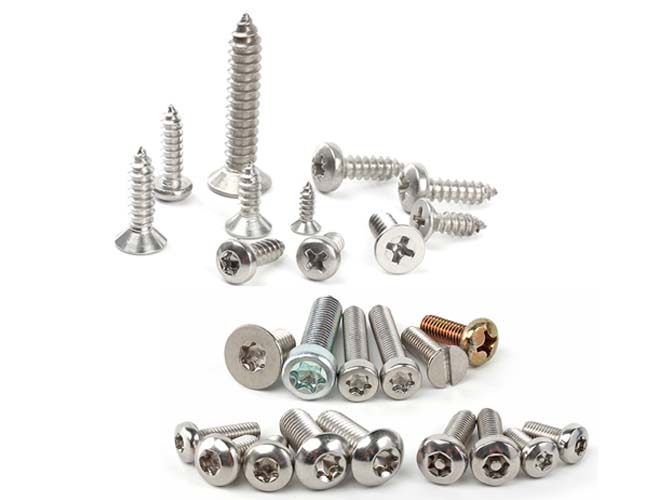
The thread-forming mechanism does not determine the head style. Depending on the product and standard, direct assembly screws may use pan, hexagon, flange, countersunk, button, or other head designs together with cross recesses, internal hex, hexalobular drives, external hex drives, or other systems.
Select the head and drive according to:
- Available tool clearance.
- Required bearing area.
- Need for a flush or projecting surface.
- Automated or manual installation.
- Required drive engagement.
- Appearance and service-access requirements.
- Strength of the material beneath the screw head.
For thin plastic covers or sheet metal, a larger bearing surface may help distribute load, but head geometry should still be verified against the assembly design.
Material, Heat Treatment and Coating
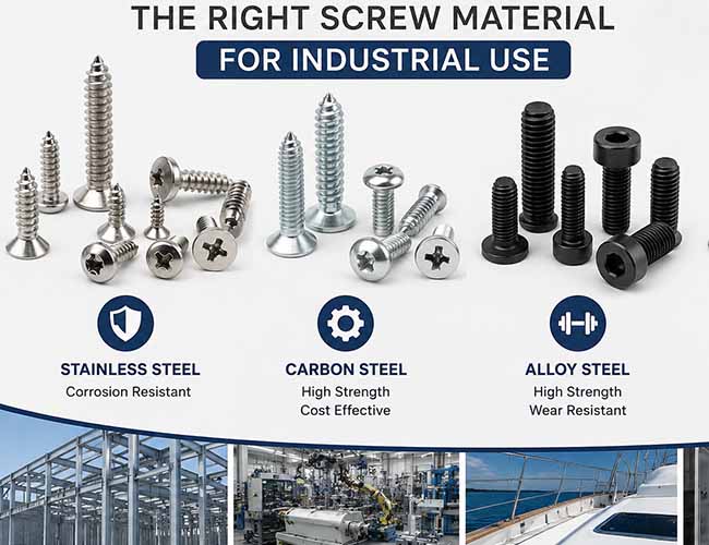
Steel direct assembly screws often require controlled hardness or heat treatment so the screw can form or cut the mating material without excessive deformation of its own thread. The applicable requirement depends on the screw standard, geometry, size, and application.
Stainless steel may be requested where corrosion resistance is important, but buyers should not assume that a stainless version of a hardened steel thread-forming screw will behave identically during installation. The material properties of both the screw and mating component need review.
Surface finish also affects corrosion protection, friction, and installation torque. Zinc-based plating, zinc-flake systems, other engineered coatings, or application-specific finishes may be used according to the project. For hardened or case-hardened fasteners, coating process selection and hydrogen-embrittlement risk should be evaluated where applicable.
Thread Forming vs Thread Cutting Screws: Selection Guide
| Application Condition | Option to Evaluate | Reason |
|---|---|---|
| Chip contamination is undesirable | Thread-forming screw | Forms the mating thread primarily by material displacement |
| Mating material can tolerate controlled plastic deformation | Thread-forming screw | Direct thread formation may eliminate a separate tapping operation |
| Material displacement creates excessive stress | Thread-cutting screw or alternative design | Cutting may reduce the amount of material that must be displaced |
| Blind hole with contamination-sensitive assembly | Careful engineering review | Cutting chips and available bottom clearance must be considered |
| Thermoplastic boss | Plastic-specific direct assembly screw | Thread and boss geometry should match the actual resin and application |
| High-volume sheet-metal assembly | Thread-forming screw may be evaluated | Can combine thread creation and fastening if the hole and material are suitable |
| Brittle or unusual material | Application testing required | Neither forming nor cutting suitability should be assumed without validation |
Quality Control for Direct Assembly Screws
Quality inspection should cover the characteristics that control the thread-creation process. Depending on the specification, this may include screw diameter, thread geometry, head dimensions, drive geometry, length, material documentation, surface hardness or case condition, coating thickness, surface appearance, and mechanical testing.
Application testing can be equally important. Buyers may need to define forming or cutting torque, drive torque, stripping torque, installation depth, pull-out performance, or other joint-specific criteria using representative components.
Flybear’s quality control support includes dimensional and thread inspection, material and certificate review, hardness and tensile testing, coating inspection, salt-spray testing when required, and other agreed inspection requirements. Application-specific acceptance methods should be defined before production.
Common Purchasing Mistakes
- Using “self-tapping screw” as the complete specification. Clarify whether the screw forms, cuts, rolls, drills, or uses another thread-creation method.
- Ignoring pilot-hole dimensions. Hole diameter and condition strongly affect installation torque and thread quality.
- Using the same pilot hole for every material. Steel, aluminum, plastic, and reinforced polymer can require different hole designs.
- Ignoring chip generation. Thread-cutting debris can matter in enclosed or contamination-sensitive assemblies.
- Choosing a plastic screw without naming the resin. Plastic type, reinforcement, boss design, and temperature affect joint behavior.
- Specifying tightening torque without assembly trials. Forming or cutting torque is part of the total installation process.
- Assuming standard numbers define every requirement. Material, finish, head, drive, inspection, and application requirements may need separate specification.
- Changing screw type without testing the mating component. A thread-forming and thread-cutting screw of similar nominal size can create very different stresses and internal threads.
When a Custom Direct Assembly Screw Is Needed
A standard screw may not fit every OEM application. Special requirements can include non-standard thread geometry, controlled forming lobes, special cutting features, reduced head height, flange heads, captive features, unusual materials, custom lengths, coatings, or application-specific drive designs.
For these projects, buyers can submit drawings, samples, and mating-component information for custom fastener review. The drawing should identify critical dimensions and tolerances, but the RFQ should also describe the mating material and installation requirement because direct assembly performance depends on both components.
RFQ Checklist for Thread-Forming and Thread-Cutting Screws
For a technically useful quotation, provide:
- Required screw standard or controlled drawing.
- Whether thread forming, thread cutting, or another direct-fastening method is required.
- Screw diameter, thread specification, and length.
- Head style and drive type.
- Screw material and required mechanical or hardness properties.
- Heat-treatment requirements where applicable.
- Surface finish, coating, lubrication, or corrosion requirements.
- Mating material, including metal grade or plastic resin where available.
- Sheet thickness, boss dimensions, or engagement length.
- Pilot-hole diameter, tolerance, depth, and hole-production method.
- Order quantity and expected annual volume where relevant.
- Installation method, speed, and torque requirements if controlled.
- Critical inspection, testing, certificate, and traceability requirements.
FAQ
What is the main difference between thread-forming and thread-cutting screws?
A thread-forming screw primarily displaces mating material to create the internal thread, while a thread-cutting screw removes material using cutting features. This changes chip generation, installation torque, pilot-hole requirements, and material suitability.
Are thread-forming screws self-tapping screws?
They can fall within the broader self-tapping category, but self-tapping screws are not limited to thread-forming designs. The term can include different methods of creating the mating thread, so the actual screw geometry should be specified.
Which type is better for sheet metal?
It depends on the sheet material, hardness, thickness, pilot hole, engagement, joint load, and assembly process. Thread-forming screws can be attractive for suitable ductile sheet materials, but production testing should confirm the required hole size and installation window.
Which screw type should be used for plastic?
The correct choice depends on the specific polymer, reinforcement, boss geometry, temperature, and joint requirements. Plastic-specific direct assembly screws should be evaluated using the actual molded component rather than selected from a generic rule.
Do thread-cutting screws produce chips?
Yes, cutting the mating thread can generate chips or swarf. The amount and behavior depend on the screw and mating material, so chip evacuation and contamination should be considered during assembly design.
What should buyers send to an industrial screw supplier?
Provide the standard or drawing, screw size and thread, head and drive, material, finish, quantity, mating material, pilot-hole dimensions, application, installation requirements, and required inspection or certificate documents.
Conclusion
The decision between thread forming vs thread cutting screws should be based on how the mating material responds during direct assembly. Thread-forming screws create the internal thread mainly by displacement and can reduce chip generation, while thread-cutting screws remove material and can be useful where a cutting action better matches the component. Neither method is universally superior.
For reliable OEM sourcing, evaluate the screw together with the pilot hole, metal or plastic material, engagement length, installation torque, head and drive, coating, and inspection requirements. Production trials are especially important for high-volume sheet-metal and plastic assemblies where small changes in material or hole dimensions can affect fastening performance.
For standard or project-specific direct assembly screws, Flybear can support technical requirement review and quotation. Send your standard or drawing, screw dimensions, mating material, pilot-hole information, finish, quantity, application, and inspection requirements through the Flybear contact page.